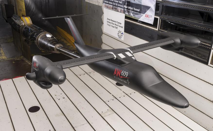
AW609 TiltRotor Wind Tunnel Testing via Composite 3D Printing
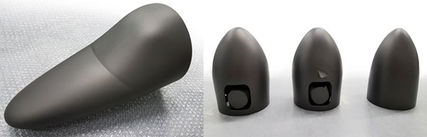
CRP Technology’s Windform XT 2.0 carbon-composite material was used to create the model via selective laser sintering.

Image courtesy of Leonardo HD.
Latest News
January 28, 2019
CRP Technology manufactured a new wind tunnel model of the Leonardo AW609 TiltRotor for Leonardo Helicopter Division (Leonardo HD, formerly known as Agusta Westland). It highlights the perfect union between selective laser sintering (SLS) 3D printing technology and CRP’s Windform high-performance composite materials. Thanks to the Windform materials, it was possible to complete and test the model in the wind tunnel within a very short time, with excellent results and with high-performing mechanical and aerodynamic properties.
The project related to the manufacturing of some external parts (nose and cockpit, rear fuselage, nacelles, external fuel tanks, fairings) of the wind tunnel model (1:8.5 scale) for the prototype of the new Leonardo HD TiltRotor AW609, made by SLS technology and Windform XT 2.0 carbon-composite material, both supplied by CRP Technology.
This wind tunnel model was designed, manufactured and assembled under the supervision of Leonardo Helicopter Division by Metaltech S.r.l. for a series of dedicated low speed wind tunnel tests.
The low-speed wind tunnel tests were intended to cover a standard range of flight attitudes to be performed at Leonardo HD wind tunnel facility and at Politecnico of Milan for the high angles of flight envelope. During the different test sessions various external geometries have been changed and checked in order to understand all the aerodynamic phenomena.
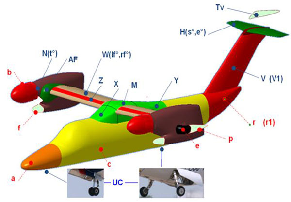
The external main components redesigned and manufactured include: fuselage and nose components, fairings, nacelles and spinner shapes, empennage, wings and flaperons.
Wind Tunnel Test Goals
Leonardo Helicopter Division’s main goals, and therefore the reasons why they have been referring to CRP Technology, have been essentially the following aspects:
- The requirement of a very short timetable, but with the highest level of reliability and commonality, in order to manufacture the external parts for the wind tunnel model;
- The research of materials with high mechanical and aerodynamic characteristics for these components that usually would have been made by a classic composite material
- To design and manufacture an aluminum alloy internal main structure suitable to be easily implemented with new geometries for the future aircraft versions or improved solutions.
This detail is crucial to the applied loads to be sustainable, and therefore they can’t be underestimated. In fact, the aerodynamic loads by the wind in the tunnel are very high. The most critical aspect of the project is therefore the resistance to the loads, but also the necessity to maintain good dimensional tolerances of such a large dimensioned component under load. It is important that the components of the external fairings don’t deflect too much under load.
In addition, even when there are no external loads, the product must have dimensional characteristics in respect of the supplied specifications.
It is important to remember that the performance of these components affects the final performance of the entire project, especially because the external fairings have to transfer the aerodynamic loads generated by the fuselage to the internal frame.
Wind Tunnel Model Design Conditions
To assure the model capacity could withstand the loads expected during the various wind tunnel testing phases, stress and strain calculation were performed. Such structural strength assessments have been executed for all the critical model components and for the assigned loading conditions.
The envelope of the expected model load conditions, obtained by scaling the full scale reference values, is fundamental to enable the requested structural evaluation and allow for a model components final design capable to guarantee the model full compatibility with both wind tunnel constraints (e.g. supports) and equipment (e.g. internal/external balances).
Model components materials and related stress limitations, stress concentrations, fatigue, etc. have discussed during the design phase.
Composite 3D Printing Model Manufacturing Techniques
Wind tunnel model manufacturing techniques have changed over the years. Historically, such components would have been made by a classic composite material technology. The restrictions of this technology were generally the long manufacturing time.
Leonardo HD’s first wind tunnel models were manufactured using woods and metallic components and then changed to a mixed solution of wood and composite fiber materials. Nowadays, all the models are manufactured using CAD-CAM approach; an internal structural aluminum and steel frame is milled and assembled and all the external geometries are obtained through 3D printing techniques.
Advanced 3D printing combined to the Windform XT 2.0 material has instead immediately convinced Leonardo HD, thanks to its very short manufacturing time and high-performance features.
Composite Material Design Process and Result
The work of CRP Technology was based on the maximization and achievement of the requested goals. It started with a careful analysis of the dimensional designs received from Leonardo HD.
The choice of the Windform XT 2.0 composite material was not casual, all the goals required by Leonardo HD were considered, such as the importance of a short realization time, good mechanical performances and also good dimensional characteristics.
Windform XT 2.0 is a carbon fiber reinforced composite 3D printing material known for its mechanical properties, appreciable for many applications such as wind tunnel, because of its high heat deflection (HDT = 173.40 °C; test method= ISO 75-2 TYPE A), superior stiffness, first-rate detail reproduction. It replaces the previous formula of Windform XT in the Windform family of composite materials: Windform XT 2.0 features improvements in mechanical properties including +8% increase in tensile strength, +22% in tensile modulus, and a +46% increase in elongation at break.
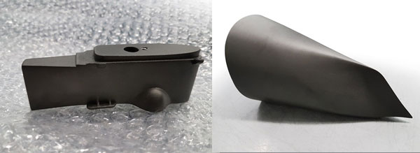
The first issue concerned the dimensions of the prototype, because some components were dimensionally superior to the construction volume of the 3D printing machines, it was necessary to separately manufacture the single parts. The experience and knowledge of this process by CRP Technology’s staff allowed the analysis, the study and the consequent creation of such a complex project without any delay or problem for the client. From the beginning, the work was focused on the design of the components, with a correct split of the parts, considering of course the working conditions and the stress that the components would have to sustain.
Identifying the parts to split was an operation undertaken with CAD software, evaluating the functional measures of the working volume but also the possibility of optimizing such volume and minimizing the production time and costs. The CAD cut was done with a technique used to maximize the contact surface in the place where the structural adhesive would be applied in order for the big parts but thin parts to resist stress.
The manufacturing time of the single parts was really short. Not much more than one day was necessary to manufacture the jobs to set on the 3D printing machines and, after four manufacturing days, all the various parts of the components were physically created.
Different confidential efficiencies, which are an integral part of CRP Technology’s specific know-how, allowed the reduction of the delivery lead time and allowed CRP to minimize the normal tolerances of this technology, and eradicate any potential problem of deformation or out of tolerance.
The final step was the complete model surface finishing, directly mounted on the rig assembly in order to optimize the small imperfections that could have come from the union of the single components. The surface of the whole model was flattened in an efficient way and treated with a special liquid that also waterproofs and prepares the surface to be painted.
All the model parts were then mounted and adapted to the main model structure thanks to a dedicated rig and assembled by Metaltech S.r.l. The final result, in line with the timetable and characteristics of the part, has been tested in the Leonardo HD wind tunnel facility at Bresso (Mi).
New 1:6 Model Created for NASA Ames Unitary Plant
As part of a thorough review of the aircraft behavior, Leonardo Helicopter Division performed a high-speed wind tunnel test campaign at NASA Ames. After a thorough assessment, the NASA Ames Unitary Plant 11x11-ft. transonic wind tunnel was selected to obtain an accurate characterization of the aircraft in full-scale conditions up to the highest speeds. The facility’s pressurized transonic wind tunnel is able to achieve full-scale Mach numbers and Reynolds numbers close to full scale.
To speed up the manufacturing process for this model, the external fuselage and additional components were manufactured using the same approach chosen for the low-speed AW609 model: selective laser sintering technology and Windform XT 2.0 Carbon-composite material.
The parts were manufactured by CRP USA, based in Mooresville, NC under the control of the model supplier ATI Co., Newport News, VA.
CRP USA demonstrated how the use of Windform composite materials, originally developed for the motorsports industry by CRP Technology, is now finding many uses in space and aerospace exploration. It was the first time Windform XT 2.0 was used for a high-speed model tested at NASA Ames facility.
The architecture of the new 1:6 model for transonic high speed tests is similar to the AW609 model but with some improvements in order to have the remote controls for the flaperons and elevator surfaces. Moreover, the use of four different 6-component strain gauge balances allowed the acquisition of all the loads acting on the complete model, the wing alone, the nacelle and the tail surfaces.
The 1:6 model scale was selected to be fully compatible within the given constraints of the physical size of the NASA 11x11-ft. tunnel. The model span was almost 2 m. It was constructed to allow for mounting in the NASA 11x11-ft. transonic tunnel, on a single strut straight sting support system.
This testing encompassed speeds between Mach 0.2 to Mach 0.6 with high Reynolds numbers and a wide range of angle of attach and side slip.
More CRP Technology Coverage
For More Info
This article was provided by CRP Technology.
Subscribe to our FREE magazine, FREE email newsletters or both!
Latest News