Field-Driven Design for Rapid Engineering and Collaboration
A new approach to multifunctional design uses fields to encapsulate shape, physics and manufacturing process in a single, unified environment.
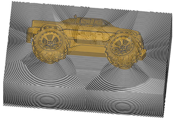
Bands of a distance field generated from a small assembly. This field extends through 3D space and stores part geometry in exact form, allowing failure-proof and nearly-instantaneous offset and blend operations. The concepts of tolerance only apply upon exporting to an image, mesh for simulation, or tool paths for manufacturing. Image courtesy of nTopology.

Latest News
May 29, 2019
The increased sophistication of today’s products and corresponding introduction of advanced manufacturing creates an unprecedented level of complexity across engineering disciplines. In particular, next-generation products—that show improved performance and efficiency, promote part consolidation, and use advanced manufacturing—all create challenges for design, simulation, and manufacturing teams. Yet technology advances now also extend to the digital authoring software that helps create products.
The Unifying Language of Fields
A new approach to multifunctional design using fields encapsulates shape, physics, and manufacturing process in a single, unified environment. The foundation of computational engineering, this field-based design methodology enables product development teams to overlay and integrate computer-aided design geometry, simulated and empirical engineering data, and manufacturing-process knowledge to design highly fit, knowledge-driven, application-specific components that scale from the lab to predictable, repeatable production.
Engineering and manufacturing is filled with fields. By “fields” we mean information about positions in space, such as distance, forces, and velocities. It turns out that almost all kinds of engineering data can be consolidated in the language of fields. Not only do CAD, computer-aided engineering and computer-aided manufacturing translate to fields, but users can also directly describe the operating environment with fields to create or modify designs.
Fields Represent Geometry
Although traditional boundary representation, or “BRep” for short, and mesh-based CAD systems do not speak the language of fields, CAD models can be converted to an implicit distance field representation to enable robust and fully automated modeling, as recently discussed in this post.
Some generative technology, such as topology optimization, directly produces field output in the form of density or distance-like fields. Even data such as point clouds and volumetric scans can be evaluated as fields without time consuming reconstruction.
Fields are the language of physics
Most types of engineering simulation, such as finite element analysis and computational fluid dynamics, use fields as their main input and output language. Each kind of solver takes boundary condition input (which generalizes as fields) and produces fields as output. For example:
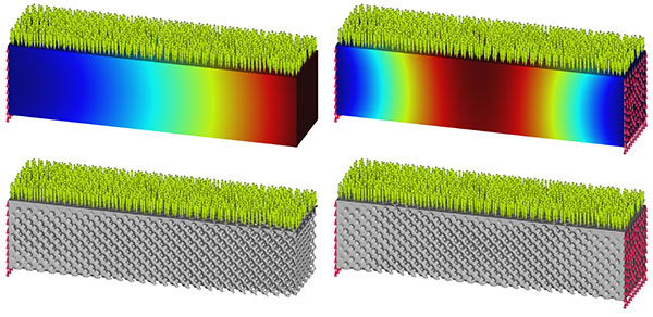
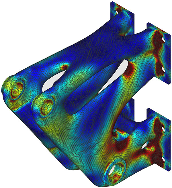
- Structural solvers produce stress, strain, and displacement fields.
- Thermal solvers produce temperature fields.
- Modal solvers produce structural fields as a function of frequency.
- Fluid dynamic solvers take flow rates and generate potential and velocity fields.
- Electromagnetic solvers work with forces, currents, and electromagnetic fields.
Fields Enable Collaboration and Automation
Traditional CAD, CAE, and CAM tools, by definition, focus on one part of the engineering process. In addition, the engineering software stack is fragmented, resulting in data models that are also fragmented. Today’s engineering environment is cluttered by the multiple applications, models, and underlying representations needed for design, simulation, and manufacturing. In all but the smallest companies, each role becomes specialized and disparate.
Geometric constraints and engineering requirements should directly drive manufacturing output, bypassing many of the iteration loops and inefficiencies associated with traditional processes. The first step in making that happen is to realize that CAD-heavy processes can lock down engineering prematurely. Before committing to detailed designs in CAD, each discipline should bring their expertise as an input to the process. Typically, there are three kinds of inputs:
- Geometric input includes concept models, the space or “envelope” in which the part may exist, mounting points and mating geometry, and aesthetic, aerodynamic, or other sacrosanct surfaces.
- Engineering input consists of simulated and empirical data about the operating or environmental conditions imposed on the part, some of which may be known a priori or learned post facto from prototyping.
- Manufacturing input can simply be simulated or measured distortion and process-specific constraints. In advanced manufacturing, it can include generative rules and sophisticated models that automate the creation of lattices, infill geometries, and compensation, preparation, and fixturing for post processing.
In field-driven design, users overlay the design, analysis, and manufacturing disciplines into one engineering model. Field-based geometry, simulation, and manufacturing algorithms can then leverage those fields to generate consistent and predictable results. This kind of computational engineering approach enables orders of magnitude increase in design-iteration speed.
In the field-based world, CAD continues to drive and document input geometry, while topology optimization enables a smooth representation of both shape and internal forces. Known environmental factors such as forces, pressures, displacements, and conductive heat transfer can overlay the nominal geometry, and effects that must be measured from prototypes, such as modal effects and convective heat transfer, can be layered on once known.
In advanced manufacturing, the manufacturing team has the most to contribute to the engineering process. Where traditional manufacturing may allow a one-way workflow from design to production, the role is reversed with advanced manufacturing. Engineers must do bench work to qualify and characterize the new processes and are the first to learn how to apply them to engineering problems. The challenge is how to share such knowledge with the rest of the engineering, design, and analysis team. Again, fields provide the common language needed to overlay the manufacturing solution with the geometry and engineering problem.
Subscribe to our FREE magazine, FREE email newsletters or both!
Latest News