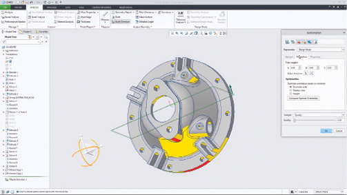
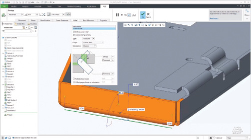
The new build direction command enables users to analyze the best positioning of a part on a theoretical build tray. Images courtesy of David Cohn.

Latest News
June 1, 2019
In 1988, PTC launched the world’s first parametric, associative feature-based solid modeling program. In 1998, the company’s Windchill software helped usher in the age of internet-based product lifecycle management (PLM).
After acquiring CoCreate in 2007, PTC integrated that program’s direct modeling technology with the parametric functionality of Pro/ENGINEER, creating Creo. After shipping the first version of Creo in 2010, the company has delivered a major update approximately every two years. Though it appears that schedule ramped up with the March release of PTC Creo 6.0, just one year after the previous version.
The latest version of the company’s flagship design and engineering CAD software offers new capabilities in augmented reality (AR), real-time simulation and design for additive manufacturing, along with numerous productivity enhancements.
PTC’s Pro/ENGINEER had a reputation for being expensive and difficult to use. Creo is different. A basic Creo license starts at $2,300 for a one-year locked subscription or $2,800 for a floating license, although adding multiple extensions can dramatically increase the cost. Not to mention, more advanced levels cost considerably more. That said, getting started with Creo is quite easy. You can download a 30-day free trial of Creo 6.0 and start learning to use the software immediately, aided by an online tutorial with sample files.
Creo 6.0 sports a standard Windows interface that includes a customizable Quick Access Toolbar and a context-sensitive ribbon across the top of the screen. A navigation panel with tabs for the Model Tree, Folder Browser and Favorites functions sits to the left of the graphics window, while a status bar and selection filter appear along the bottom.
There are also mini-toolbars that open within the graphics window when performing certain tasks. For example, when you select an edge in the model, a mini-toolbar provides options for editing dimensions and adding a chamfer or round.
You can toggle the navigation panel on and off and expand or collapse the model tree. When you select an object in the model, it highlights in the model tree, and vice versa. You can also switch to a full-screen mode, which enlarges the graphics area to fill the entire screen, with no other user interface elements visible except for the mini-toolbars. Though when you move your mouse to the top of the screen, the ribbon reappears so you can select an operation.
Five Levels of Creo
PTC offers five Creo design packages. Design Essentials includes 3D part and assembly design, automated 2D drawing creation, parametric and freestyle surfacing, assembly management, sheet metal design, mechanism design, plastic part design, direct modeling, additive manufacturing, AR and the ability to work with data from SolidWorks and Autodesk Inventor.
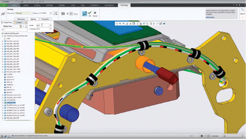
Users can also create and optimize pipe and cable routing, produce photorealistic images, perform static structural analysis as well as simulate parts and assemblies.
Creo Design Advanced adds prismatic and multi-surface milling, top-down design and concurrent engineering capabilities. Design Advanced Plus includes all the Essentials and Essentials Plus features, and adds advanced surfaces, additive manufacturing, geometric dimensioning and tolerancing and tolerance analysis, and model design and machining.
Those needing even more advanced capabilities can purchase Creo Design Premium, which adds Fatigue Advisor, computational fluid dynamics (CFD) for flow analysis, collaboration extensions for CATIA and NX, NC sheet metal, four-axis turning and wire electrical discharge machining and PTC Mathcad.
The top-of-the-line Creo Design Premium Plus adds even more advanced simulation, machining and CFD analysis, an Options Modeler, topology optimization and the ability to connect to 3D metal printers and automatically generate 3D metal support structures.
A Host of Enhancements
Creo 6.0 offers a number of core enhancements. For example, in addition to the mini-toolbars, the new release expands on Creo’s model-based definition tools with improved workflows for creating and editing notes and dimensions and improved parent/child behavior for annotations. There are also new configuration options for displaying dimensions and for sharper highlighting of edges. This improves visibility for objects that are frequently used in the graphics window. Dimension positions are also better preserved when sketching, and the appearance of the model tree is easier to control.
You can also now create a helical curve object when creating a volume helical sweep or a helical sweep and then use the curve for downstream actions, such as for visualization in 2D views on a drawing. But the biggest improvements in Creo 6.0 come in the areas of additive manufacturing and collaboration using AR.
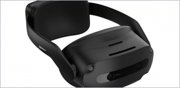
Creo 5.0 users could publish up to five AR experiences of a model and then let anyone visualize them using a free app, but you needed a premium account to control access for AR publishing, sharing and viewing. The AR tools in Creo 6.0 now enable every user to publish and manage up to 10 designs, control who has access to each model, and easily remove old ones at will. In addition, users can now view AR models using the Microsoft HoloLens headset.
This release also adds new capabilities for additive manufacturing. In addition to standard 2.5D and 3D lattices, there are three new formula-driven cell types: gyroid, primitive and diamond. Using these cell types, you can create self-supporting lattice geometry.
Variable density is also supported, minimizing the support structures that are required for 3D printed parts. Beam-based stochastic lattices are also available, providing an alternative to uniformly distributed lattices, so that sandwich-type structures are better filled. You can also define your own custom lattices using Creo geometry.
The new build direction command enables users to quickly analyze the best positioning of a part on a theoretical build tray. This helps reduce print time, minimize support structures or maximize tray use, and can be leveraged to drive the lattice design. Creo 6.0 also supports slicing for 3D printing.
For subtractive manufacturing, you can now control the tilting of the tool when performing profile turning. This prevents tool collisions and ensures that all areas are reached for machining.
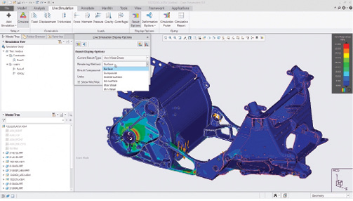
Creo Simulation Live lets you perform thermal, model and structural analysis on designs as you work.
Creo 6.0 also introduces real-time simulation with Creo Simulation Live, powered by ANSYS. Now you can get real-time guidance on design decisions as you make them. Creo Simulation Live runs in the background, providing instant feedback as you make changes to your design. Creo Simulation Live works on parts and assemblies, providing structural, thermal and modal analysis so you can iterate more quickly and design with greater confidence.
Other Improvements
For those working with electrical components, Creo 6.0 reduces by half the number of clicks needed to define and place tie wraps and markers and there are new capabilities providing users with greater control to place those features more efficiently.
For example, you can control the placement of tie wraps and markers from either end of the cable, save clicks with a new repeat command and even let Creo automatically designate a name for the tie wrap and marker. Then, when the design is checked into Windchill, you can see the tie wraps and markers in the bill of materials.
The sheet metal user interface has been enhanced and regeneration performance improved for sheet metal cuts. In addition, sheet metal wall features now automatically detect neighboring walls and create corner reliefs and corner seams.
Creo’s Intelligent Fastener Extension (IFX) lets you migrate legacy fasteners into the existing library to create your own customized library. Creo 6.0 now has support for multiple holes, the ability to check if the fastener already exists and easy access to commands in the mini-toolbar.
Other program improvements include a modernized Chart Tool for better control over chart settings, the ability to output a motion sequence from a mechanism or design animation to create a high-quality video and updates to the default depth used in the Extrude tool to avoid zooming interactions.
When doing simulation in Creo 5.0, topology optimization was limited to individual parts. In Creo 6.0, you can define and run a topology optimization study of a component in an assembly. Although only a single component of the assembly is optimized, the optimization leverages the loading conditions of the complete assembly.
Every level of Creo includes PTC’s Human Factors Design tools, which enable users to quickly insert and customize digital human models to study ergonomic issues, such as human reach and vision. An eLearning Library provides more than 140 hours of training. When you need to work remotely, you can borrow a floating license for up to 180 days.
Each package also includes a home use license of the Creo Parametric Essentials package. And the Creo Performance Advisor provides a dashboard for your entire Creo installation, allowing you to understand and optimize system performance.
Links to download a free 30-day trial of Creo 6.0 are easy to find on the PTC website. You can also download a trial of Creo Simulation Live. With the latest release, PTC continues to extend the power of its parametric CAD software, providing an extensive product lineup.
More PTC Coverage
Subscribe to our FREE magazine, FREE email newsletters or both!
Latest News
About the Author
David Cohn is a consultant and technical writer based in Bellingham, WA, and has been benchmarking PCs since 1984. He is a Contributing Editor to Digital Engineering, the former senior content manager at 4D Technologies, and the author of more than a dozen books. Email at david@dscohn.com or visit his website at www.dscohn.com.
Follow DE