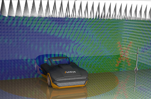
A full simulation of the ISO 11451-2 test enables connected car makers to predict the behavior of antennas, absorber elements and electronics embedded in vehicles before the first physical prototype is available. Image courtesy of Ansys.
Latest News
September 29, 2022
The connected car is a game changer for automotive engineers. No longer can conventional practices, technologies and tools get the job done. Forced to confront an almost unprecedented level of complexity, designers of the wireless infrastructures that support the connected car must contend with a massive increase in data traffic, a plethora of increasingly sophisticated radio frequency (RF) and a densely populated operating area in which the interactions of subsystems all too often confound optimum performance.
To overcome these hurdles and achieve harmony among all constituent subsystems, wireless system designers must adopt advanced multiphysics design practices and tools and change how, when and by whom simulation is used in the development process.
This raises the question: Where does digital twin fit into this scenario?
A Changing RF Landscape
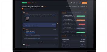
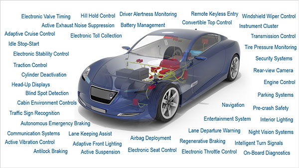
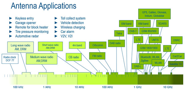
Perhaps the greatest hurdle facing designers of the connected car’s wireless systems is the sheer number of factors and variables that affect the vehicle’s overall performance [Fig. 1]. This already complex design problem is further complicated by the effects of the interplay among wireless and nonwireless subsystems. Combined, these issues overwhelm older RF technologies, making them an impossible choice for the designer.
“As the number of sensors, infotainment options, autonomous applications and electric vehicle advances continue to increase, the amount of data processing required by the electrical systems in present and future automobiles is rapidly increasing,” says Wade Smith, application engineering manager at Ansys.
Smith explains that the greater volume of data demands faster processing and data transmission. He gives an example of how sensors such as cameras may need data rates as high as multiple Gbps. “If other sensors such as lidar, radar and ultrasound are added, the required data rates increase dramatically. The old [controller area] networks in cars just don’t work anymore,” he says.
As connected car companies search for alternatives to legacy technologies, their design teams have begun to look to standards like automotive ethernet and SerDes standards to help push potential automotive data rate capabilities up to 100 Gbps. Pushing high data rates like these through chip packages, into printed circuit boards (PCBs), through connectors and into multiple meters of cables in an automotive environment, however, can pose a tough signal integrity problem.
Complicating matters further, various choices extend beyond digital signal handling to wireless networking technologies. Options such as Bluetooth, multi-band Wi-Fi, GPS, Zigbee, LTE, 5G, radar and various wireless sensors are becoming more standard in vehicles. For applications such as gaming, infotainment and vehicle to everything (V2X), low-latency data links may be needed, especially for advanced driver assistance systems (ADAS) that communicate with sensors implanted in smart city environments.
“This multitude of wireless options requires various antennas to be strategically placed within the car,” says Smith. “These antennas and their radio systems have to work without interfering with each other and the other electrical systems within the car. This can be a complex lab test, especially when designers are trying to optimize the placement of the antennas for various vehicle types.”
Another issue that can arise relates to components purchased from vendors that usually test the products in an isolated environment. These components may pass electromagnetic compatibility and other tests when evaluated outside of the automobile, but inside the automobile, the components may operate differently because signal return paths differ, or the component may find itself inside a cavity resonance.
“There are times when the manufacturer’s recommendations can’t always be followed due to volume where the device may need to be placed,” says Smith.
EMI Can Be a Ubiquitous Problem
Electromagnetic interference (EMI) is another issue that challenges designers of connected car wireless systems face, as it can degrade or interrupt wireless transmissions. This interference typically stems from systems that operate close to the frequency band in which other connected car applications operate.
Much of this unwanted noise comes from inside the vehicle, with sources ranging from antennas, infotainment systems and sensors to control computers, batteries and automotive buses. Perhaps the greatest EMI sources, however, are the power management systems that power resident electrical systems.
“These systems typically employ multiple buck/boost DC/DC converter combinations,” says Smith. “These switching converters are notorious for increasing the harmonic noise content of power rail systems, which increases the EMI of the systems. Locating EMI issues when various power converters are employed can be a nightmarish scenario for engineers in the test lab.”
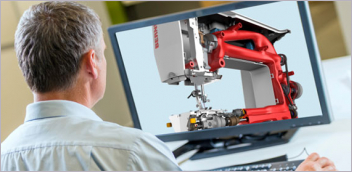
EMI sources, however, are not limited to internal sources. Outside the vehicle, radar beams and reflections from other vehicles’ sensors can also interfere with wireless signals [Fig. 2].
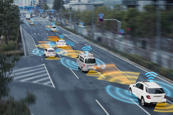
Fig. 2: Electromagnetic interference with connected car wireless communications can come from sources beyond the vehicle, such as reflections from other vehicles’ sensors. In response, automotive engineers must simulate each noise source and increase shielding on each vehicle subsystem as necessary. Image courtesy of Dassault Systèmes.
The type of vehicle in question can also help determine EMI source and quantity. For example, if the vehicle has an internal combustion engine, major sources of EMI include the starter and ignition systems.
On the other hand, if the vehicle uses an electric motor, EMI sources can include complex battery systems and charging systems.
All such systems can potentially produce harmonic content that interferes with the performance of the wireless components of the automobile.
Achieving Wireless Coexistence
Another major design issue stems from the increase in wireless technologies implemented in the connected car. Wireless systems such as V2X and 5G allow cars to use frequency bands that are very close to frequency bands already used by other wireless systems. For these systems to co-exist, bandpass filters with very tight bandwidths, low insertion loss and a high resistance to environmental changes (such as temperature) must be used.
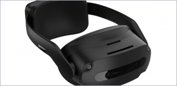
The problems created by densely positioned wireless subsystems is further compounded by interference created by antennas [Fig. 3].
“Multiple antennas by nature interfere with each other,” says Daniel Kienemund, technical product manager at Siemens Digital Industries Software.
More Sensors Mean More Complexity
Another factor that is hindering further development of connected car wireless infrastructures is the exponential growth of sensor deployments. The expanding footprint of these devices especially complicates the design of RF systems on multiple levels.
For example, increasing in direct proportion to the growing number of sensors, EMI and radio frequency interference (RFI) occurs not only between sensors but also between sensors residing on other connected vehicles. This is particularly true of more advanced vehicle designs.
“The increase of both EMI and RF interference is especially true in electric vehicles with [advanced driver assistance systems (ADAS)],” says Rick Sturgeon, senior director of transportation and mobility, Dassault Systèmes. “Engineers must therefore optimize each subsystem to reduce interference.
“In addition,” adds Sturgeon, “engineers can further reduce interference with other sensors by carefully considering both the placement and orientation of ADAS sensors on the vehicle.”
The growing sensor population also potentially leads to an increase in the number of vendors, which can be problematic for simulations because not all vendors provide reliable and accurate models of their products.
Frontloading Simulation
The complexity of connected car designs in general, and the intricacies of their wireless infrastructures in particular, pose daunting challenges for automotive development teams. For these designers, success is determined by the team’s ability to analyze a plethora of variables, juggle multiple technologies, factor in their interactions and ensure optimal performance.
“Engineers need to analyze many components and their variants at different stages of development, combining all vehicle components—mechanical, electrical, electronics, sensors and software—into a single model, which is then maintained throughout the development cycle,” says Sturgeon.
This casts the original equipment manufacturer (OEM) designer in a broad role, requiring a holistic perspective.
“The automotive engineer commonly takes on the role of a system integrator,” says Kienemund. “The components are put together into a working system, specified only to a certain degree. More detailed information may simply be unavailable. The integrator, however, must ensure that the system works in various platforms and hundreds of different configurations.”
These demands are forcing connected car wireless system designers to redefine the place of modeling and simulation in the development process.
One approach that some engineers are embracing offers a way to redistribute their expanded workload. By providing simplified simulation tools to less experienced automotive design engineers, advocates of this approach aim to enable the design engineers to perform many trade-offs early in the development process, freeing up specialists for more sophisticated tasks.
“Electromagnetic simulation experts only become involved for the most demanding technical challenges,” says Sturgeon. “This phenomenon is called ‘left shift of simulation’ because experts cannot do all of the work.”
This left shift moves simulation to the early stages of the development process, from experts to designers, enabling simulation-driven design and reducing costs by avoiding corrections in later stages of the development process.
“The growing number of challenges have pushed engineers to adopt a ‘shift left’ mindset that has led to a larger interest in virtual vehicle analysis,” says Smith. As he explains, 3D CAD versions of the vehicles, and potentially their operating environment, are imported into simulation tools (for example, high-frequency electromagnetic simulation software [HFSS] or systems tool kits) to analyze, study and optimize the electrical systems. Components such as chips, chip packages, connectors and PCBs can be analyzed with tools such as RedHawk, Totem, SIwave and HFSS. Cables and cable systems can be modeled with EMA3D Cable and HFSS. These models can be linked together for accurate system-level analysis.
Using Simulation to Counter EMI and RFI
To counter the effects of EMI and RFI, automotive engineers must simulate each source of interference and increase shielding on each vehicle subsystem as necessary. To help designers perform these tasks, software providers offer a suite of simulation, antenna design, interference analysis, antenna placement and shielding effectiveness tools.
“If the focus is on RFI, such as antenna system desense, tools like HFSS can be used to allow engineers to place antenna models in different locations on vehicle CAD models to investigate how the antennas may interact with one another,” says Smith. “HFSS can be combined with tools such as EMIT to allow for the actual radio input to be injected into the antennas, thereby allowing the radio harmonics to be included in the analysis. This allows the user to quantify the actual interference between the various antenna systems in the car.”
On the other hand, if the area of interest is the EMI created by cabling systems in the automobile, software like EMA3D can be used to simulate all of the cable systems in the automobile and produce a visual display of where interference can happen. Multiple cable types also can be included and analyzed in the simulation, which can help the designer quantify the effects of various cable choices for different applications.
“If the designer wants to observe the interactions of selected components, virtual models of anechoic chambers, including commonly employed test antennas, have been created in HFSS that can be used for component-level radiated analysis all the way up to vehicle-level analysis with components included,” says Ansys’ Smith.
Lastly, EMI consists not only of radiated emissions but also conducted emissions. Conducted emissions typically consist of low-frequency harmonic energy. Therefore, components such as cables, PCBs, power converters, power transistors and transformers can be built and analyzed using tools like quasistatic field solvers—such as Maxwell and Q3D—to produce models used in system-level conducted-emission analysis.
In Pursuit of Wireless Coexistence
Development teams are constantly challenged to achieve wireless coexistence, an elusive goal considering the variety of wireless technologies and protocols in play and the number of RF devices deployed in such a small physical space.
Although a number of factors must be considered to achieve RF coexistence, many challenges center around the connected car’s antennas. Though these devices operate in different frequency bands, they still couple to a certain extent. Out-of-band energy is commonly filtered by the transceiver input filter. Because of the low special distance between co-sited antennas, however, the energy amount unwillingly received can still be magnitudes higher than the wanted signal. Therefore, in addition to filter optimization, antenna placement, orientation and polarization are still issues of interest in simulations focused on the effects of antennas on other wireless systems.
“Antenna co-site simulation addresses this issue by analyzing the coupling between antennas, taking into account the platform upon which they are installed,” says Kienemund. “From these simulations, optimized placement, orientation and polarization can be deduced to mitigate antenna interference.”
Digital Twin Provides the Whole Picture
Today’s connected car is more complex than before due to the increased number of components and subsystems that it contains. All of these design elements and their operating features must be analyzed as a multiphysics system.
To appreciate the impact of intrasystem interactions, consider the following examples.
The aerodynamic shape of the vehicle or the materials used in the fabrication of the car can affect the operation of its wireless components.
In another area, the placement of the motor components in an electric vehicle aimed at reducing road noise can also negatively affect EMI suppression within the vehicle.
Also, depending on the mechanical structure of the automobile, EM signals from telecom or other wireless sources external to the automobile can leak into the vehicle and interfere with the digital or cable system.
“Given the tight interdependencies of these various subsystems, developing and maintaining a digital twin that integrates the full functionality of all these systems has become an invaluable tool for any organization to understand their product,” says Kienemund. “We believe that the comprehensive digital twin is essential to tackle these challenges. It allows for a streamlined data transfer between OEM and suppliers, thereby coupling not only EM simulation capabilities on various scales but also enabling various disciplines of simulation to work and act together.”
More Ansys Coverage
More Siemens Digital Industries Software Coverage
Subscribe to our FREE magazine, FREE email newsletters or both!
Latest News