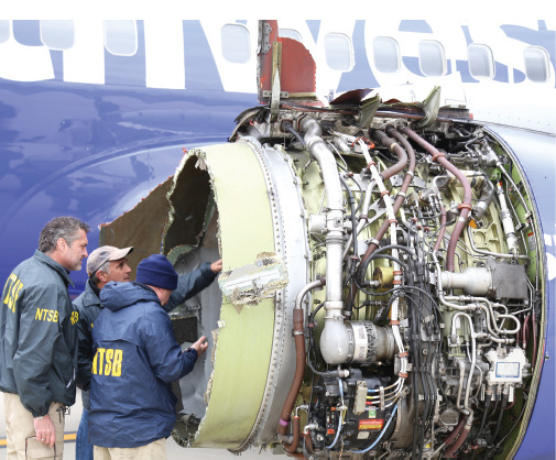
National Transportation Safety Board investigators examine the engine of Southwest Airline flight #1380. Image courtesy of NTSB.


Latest News
September 1, 2018
In April, just days after the fatal engine failure incident on Southwest Airline flight 1380, the Federal Aviation Administration (FAA) announced its intent to issue an emergency airworthiness directive.
“The directive will require an ultrasonic inspection of fan blades [of CFM56-7B engines] when they reach a certain number of takeoffs and landings. Any blades that fail the inspection will have to be replaced,” the FAA stated. The FAA’s European counterpart, the European Aviation Safety Agency, also issued a similar notice. The requirements echoed the recommendations issued by the engine manufacturer CFM International.
The culprit for the April 2018 incident was fatigue fracture on one of the fan blades in the engine (the superstitious observers couldn’t help but notice it was the No. 13 blade). “There was evidence of metal fatigue where the blade separated,” reported Robert Sumwalt, chairman of the National Transportation Safety Board. “The crack was in the interior part of the fan blade, so certainly would not be detectable looking at it from the outside,” he added.
In 2016, in another incident involving a separated fan blade in the same engine type, Southwest Airlines flight 3472 made an emergency landing in Pensacola, FL, without any passenger injury. Such incidents give us an idea of the skills and technologies used to hunt for invisible damages in aerospace components.
Lifespan Predictions and Expansions
It might make some frequent fliers uneasy to contemplate the design decisions aircraft manufacturers make, especially the trade-offs between safety and structural efficiency, but it’s a reality.
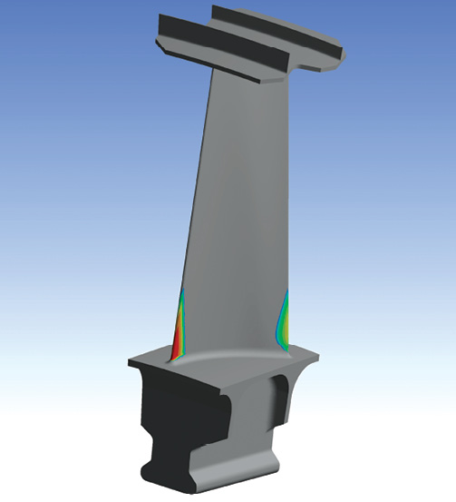
 A contour plot of the expected life of a jet engine turbine blade. Red indicates the most critical regions based on the provided loading spectrum. Image courtesy of ANSYS.
“If you design a structure without any weakness [that is, with sufficient weight, mass and material to address every conceivable failure scenario], then the structure becomes very heavy and overdesigned. So you have to accept some risks,” points out Robert Yancey, director of manufacturing production, Autodesk.
Airplane parts, however well-designed, are bound to break down from metal fatigue and wear and tear over time. Therefore, as standard maintenance, parts are inspected at different intervals to verify their airworthiness. The longer a part has been in operation, the more rigorous the inspection.
In the early phase of the part’s operational life, visual inspections may be sufficient to detect fractures and damages. As the part approaches its twilight, the potential for developing internal deteriorations increases. At this stage, in addition to visual inspections, X-ray, ultrasonic, eddy current and other technologies are employed to examine the health of the part, both inside and out.
Based on inspection results, some parts may be recommended for replacement or repair. In the latter, the intent is usually to extend the life expectancy of the part by implementing features that mitigate sustained damages. As aircraft and parts start showing signs of age, inspection procedures and requirements also get more sophisticated and complex.
When Will it Break?
You can perform a simple fatigue experiment with a paper clip. Take a paper clip, flex it at the same angle and count how many flexes it takes to break. That, in essence, is fatigue life calculation. With parts and components that are much larger, stronger and more expensive, performing the equivalent of this experiment in pixels in simulation software is much more efficient than building a rig to automatically flex or pound the part repeatedly to see how long it will last, or how much beating it can take.
“Fatigue is a mechanism related to the repeated application of cycling loads. Individually, these cycles are too small to cause failure, but added up over time they cause damage and eventually crack initiations,” explains Ashwani Goel, senior solution consultant, Dassault Systèmes SIMULIA. “The fatigue failure happens in three stages: The first stage is damage initiation. In this stage the microcracks form and develop. The second stage is the crack propagation. This is the visual lengthening of a crack. The final stage is fracture. This is where the crack has grown large enough in the structure that the remaining load path is no longer sufficient to carry the loading and the part breaks.”
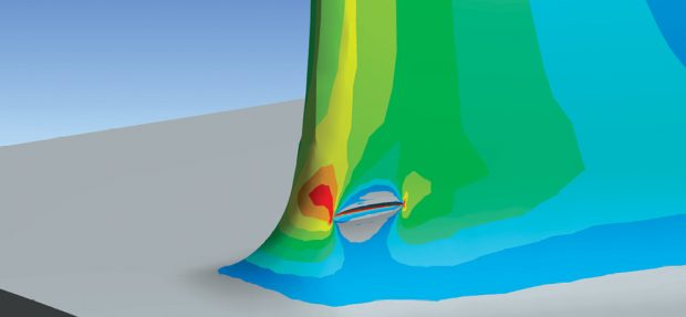
 A simulated elliptical embedded crack in a jet engine turbine blade with the stressed region highlighted in red around the crack front. The crack automatically grows during the simulation. Image courtesy of ANSYS.
“A turbine blade, for example, is expected to survive X number of takeoffs and landings. Engineers can use structural mechanics and CFD (computational fluid dynamics) simulation tools like ANSYS to determine that,” says Sean Harvey, technical services manager, ANSYS. Such calculations are reinforced by physical test findings.
“[Fatigue analysis] can be done using a workflow in which internal stresses are predicted with Abaqus [software], then fatigue analysis can be done using FE-SAFE [part of the Dassault Systèmes SIMULIA Portfolio] to predict the number of load cycles until crack initiation, followed by Abaqus again using a low-cycle fatigue procedure to predict the crack propagation and final fracture,” says Goel. “This helps identify these types of fatigue related problems not visible to the naked eye. These can address the questions like how long it will take [and where] for a crack to initiate, and then once initiated, how long it will take for the component to rupture.”
The Unexpected
Manufacturers anticipate that parts and components will encounter anomalies and unforeseen events. An engine, for example, might ingest a bird or a chunk of ice. “You may not be able to see the damage from an event like this, but you know it takes out a certain number of cycles from its original life expectancy,” says Harvey.
“Aircraft are designed with fail-safes so that, even if you miss a crack in a critical component in one inspection cycle, the failure is contained,” Harvey adds. Before joining ANSYS, he used to work for a firm that specializes in calculating helicopter blade life expectancy.
To account for these unexpected incidents, “engineers usually put in a safety factor in life expectancy calculations,” he says. “If the simulation results and physical tests suggest the part can last 10,000 hours, for example, they may scale it back by 2,000.”
One method to respond to unforeseen events is to have good reporting procedures, and to recreate the event—to the extent that’s possible—in simulation to recalculate the expected lifespan of the component, Harvey says.
Known Issues With no Easy Answers
Simulation enables the ability to see stress concentration—the general regions on a part that are subject to repeated stress. This identifies the areas vulnerable to stress, but not necessarily the precise point where cracks will initiate.
A crucial part of the inspection cycle is determining when the next inspection should occur, based on the previous inspection results and the part’s condition. Misjudging the interval means putting a risky part into service. This is where engineers grapple with the crack propagation dilemmas.
“The inspection is done in such a way to ensure the part is safe to be in use until the next inspection. There are good modeling techniques that let you predict how a flaw in small size will grow over time, over a certain number of flights. That partly factors into deciding when to inspect the aircraft again,” Yancey says.
“You want to find the cracks when they’re small; you want to catch them before they reach a certain size,” says Stuart Brown, managing principal of Veryst Engineering, a simulation and analysis service provider.
Inspection technologies and equipment—such as eddy currents, X-ray and ultrasound—have a resolution limit. “That’s the limit of the physical capability of the detection method,” says Brown. “So they cannot detect microcracks below their resolution limit.”
“If you know there’s a crack, you can simulate it. But if you don’t know it’s there, you won’t try to simulate it,” says Yancey. Before joining the design and simulation software sector, Yancey held management and executive posts at Aracor and at EWI, firms that specialize in nondestructive testing and evaluation methods.
Simulating the Inspection Methods
Because automotive and aerospace leaders are already investing in digital twins, there may be an opportunity to develop better inspection strategies by conducting virtual inspections along with the physical tests.
“Each inspection method has its own strengths and weaknesses. You can use simulation to check the performance of different methods, to determine which one is best suited for the type of crack or engine part you’re inspecting,” notes Brown.
Veryst has partnerships with COMSOL, SIMULIA and ANSYS. COMSOL, known for its multiphysics simulation, is particularly suited for certain phenomena. “For example, thermosonic crack detection, which is where you identify cracks by using sound waves to make them heat up,” Brown explains. “This technology involves sound propagation and heatwave propagation, so it’s a multiphysics problem.”
“Simulation methods combining crack initiation and crack propagation analysis methods can provide an invaluable insight into the effectiveness of inspection methods used, for example, to evaluate the condition of engine fan blades in service,” says Pawel Sobczak, senior technical specialist, Dassault Systèmes SIMULIA.
Challenges With New Materials
Because of the advantages they offer in lighweighting, composites and polymers from the additive manufacturing (AM) sector are beginning to make their way into aerospace. This raises new questions in fatigue life calculation.
“While we have investigated the characteristics of metals for centuries and therefore have a very good understanding of their behavior, composites and AM not only started to be used on a bigger scale only in the last decade or two, they keep on evolving as the technologies mature,” notes Sobczak. “From a designer and engineer perspective, it sometimes feels like chasing an ever-moving target.”
“You may know the life expectancy of steel and nickel, but that doesn’t mean you can use that to extrapolate how long a steel-nickel-alloy composite part will last,” says Harvey. “Companies like Boeing, GE and United Technologies typically have their own material labs, so they can do their own testing, but to qualify a new material [for use in building critical airplane parts] is quite expensive.”
“Testing composite materials to qualify them is more extensive, because the materials are not uniform,” says Yancey. Classic manufacturing materials such as steel respond to push, pull and stress in every direction the same way. By contrast, composites—made of woven fibers and plies of different materials—respond to forces differently in various directions, depending on the fiber orientation or the ply stack layout. It means the tests required to collect the necessary data to understand their behaviors are much more extensive.
For smaller firms with no in-house testing capacity or financial muscle to quality new materials, the best strategy would be to work with materials that have already been qualified and approved for use in the target industry, such as aerospace or automotive.
Better Insights
The sensor-driven internet of things (IoT) technologies are already having an effect on fatigue life analysis. Most aerospace suppliers and manufacturers equip engines and structures with sensors to collect data on the loads on the parts, Yancey notes. The data gives a much clearer picture of part health after each flight.
“Using real-time data related to structural loading and a virtual twin of the engine, it is feasible to follow the fatigue life of the components in the engine in near-real time,” reasons Mark Wyatt, senior business development executive, Dassault Systèmes SIMULIA. “This information can be used to inform aircraft operators of needs for additional or accelerated inspection frequencies, for example. Going a step further, the potential of complete failure could be investigated using tools such as Abaqus [or] FE-SAFE.”
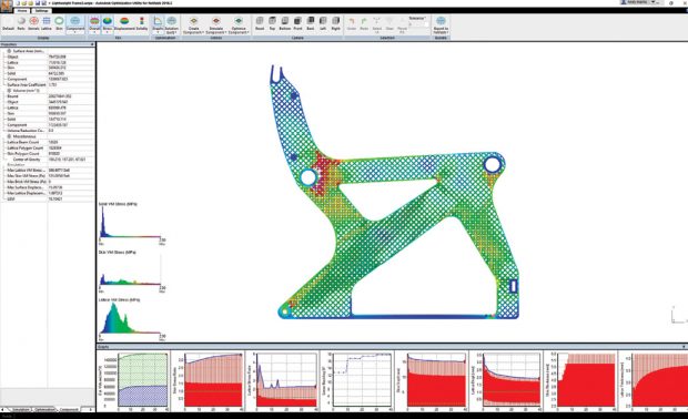 This lattice-optimized aircraft seat frame shows relatively even distribution of stress in Autodesk’s Nastran simulation software. The small area of heightened stress in red toward the rear of the seat is due to the allowance that the frame can yield at that point under an emergency landing load case. Image courtesy of Autodesk.
“The industry traditionally has been on fixed inspection schedules, but it’s now moving toward adaptive schedules,” Yancey says. “Now that aircraft manufacturers get feedback from sensors, they can develop inspection cycles based on sensor readings to inspect when inspection is required, which saves costs and improves safety.”“If you’re talking about an engine blade, ideally you might put sensors on some critical areas to collect values like rotations per minute, vibration and temperature,” says Harvey. Previously, this may have seemed impractical, but Harvey believes miniaturized electronics have made it possible. “These readouts can be fed into a digital twin, so you can use the digital twin to compute the component lifespans,” he adds.
Yancey believes generative design, an algorithm-driven approach to designing lightweight structures with sufficient durability, could contribute to better, safer parts. “Usually cracks are the result of stress concentration,” he observes. “Generative design could help come up with designs that more uniformly distribute the stress loads to avoid high stress spots.” Generative design is part of certain Autodesk design software products, such as Autodesk Fusion 360 and Autodesk Netfabb, as well as software from other vendors.
“[Fatigue analysis] has to be a combination of simulation and physical testing,” says Brown. “People performing simulation have to obtain feedback from physical tests, and vice versa. It’s not a problem that can be solved by one.”
Subscribe to our FREE magazine, FREE email newsletters or both!
Latest News
About the Author
Kenneth Wong is Digital Engineering’s resident blogger and senior editor. Email him at kennethwong@digitaleng.news or share your thoughts on this article at digitaleng.news/facebook.
Follow DE