Making PCB as easy as 1-2-3
Altium Designer provides guidance for users called to perform printed circuit board design and field programmable gate array tasks.
August 1, 2010
By Mike Hudspeth
Have you ever been on an airplane and looked out the window to notice how much the cityscape far below looks like a printed circuit board (PCB)? From the sky, most buildings look similar to electrical components—like memory modules and processors. If you’re like my wife, you don’t spend a lot of time looking out the windows of the plane. She’d rather just ignore what’s down there and let someone else worry about it.
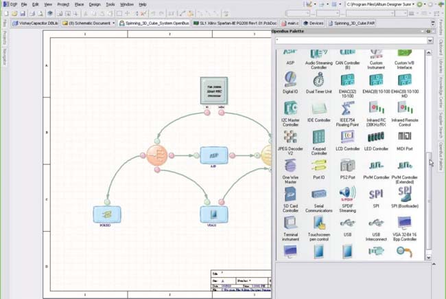
 Figure 1:Drag and Drop design greatly simplifies your designing. |
There are many people who seem to think the same way about their PCB design. As long as it works, they leave it up to their electronics people. In fact, it may sound strange to read this from an industrial designer. We aren’t usually known for our PCB designs. But in a manufacturing environment, everyone has to know a little about everything else just to stay competitive. Believe it or not, I have been called on from time to time to do some PCB design, so I’ve had to learn. Knowing about PCB design means knowing something about the tools for it. One intriguing tool is Altium Designer from Altium Limited.
As with any industry, companies abound that make software to do just about everything you could want. Altium has been in business for 25 years providing tools for electronics design, and exists for Electronic Design Automation (EDA). The company wants to quell your organizational pain points. The main two points it helps with are collaboration and process bottlenecks. And when you aren’t fussing with those, you can apply more of your energy to differentiation.
Altium Designer has broad appeal with industry. Huge numbers of companies are running this software. In 1999, the company changed its name from Protel to Altium. It used to make PCAD (which was retired in 2008) and combined it with Protel. The result was Altium Designer. But don’t get the idea that the products are merely bolted together. Unlike some of its competitors, Altium reworked its software from the ground up, so the solutions could be completely integrated and use the same database for everything—and they have some very cool capabilities.
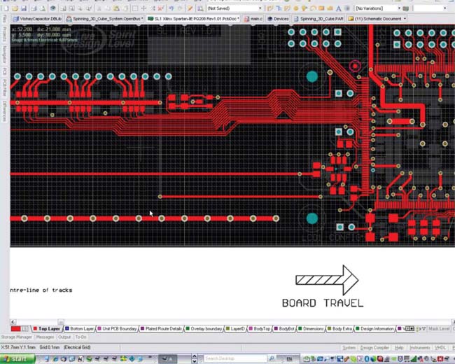
 Figure 2:With up to 48 layers, you can design some pretty complex PCBs. You can look at each layer by itself, or in context with the rest of the board. |
What is it?
Altium Designer is a System Design Platform for field programmable gate array (FPGA) and PCB design. Altium says its competitors are more like tool chain vendors: Their products were made by multiple vendors as standalones, and then bought and bolted together later. Altium describes itself instead as a platform vendor (with a platform architecture). It uses a unified data model, so nothing about its software is an afterthought. Altium Designer has a very aggressive, six-month release cycle, so it’s never going to be long before something new is on your doorstep.
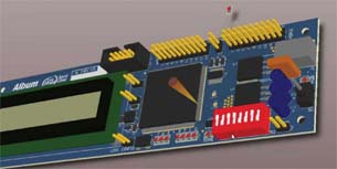
 Figure 3:With 3D visualization, you can see exactly how your boards are going to look when they come off the factory floor. |
What Does It Do?
Altium Designer is a data manager. It’s like the PDM system for electronics. That means it comes with version control. Yep, that’s right: You can manage all the different versions of your designs with this one tool. You can create and vault, check out and change—even generate ECO documentation. The Release Manager captures all the documents that go with your design (PDF, Gerber, etc.). That way, you can control all aspects of your design. The Output Job file pulls together everything in the whole project—FPGA files, PCB files, MCAD files, PDFs, Excel spreadsheets, Word documents—anything that is associated with it. That way, you can archive it off or transfer it anywhere you need to.
With difference visualization, Altium Designer can compare two files, a little like those “What’s The Difference” games you play in the newspaper. It will find everything that is different and highlight it so you can decide what to do. Altium Designer also includes a code editor for programming your soft processor, as well as a full set of FPGA libraries from which you can drag and drop components into your design (see Figure 1). Then, the software automatically generates the board-level schematics based on the FPGA you created. That makes using it very easy.
Information at your Fingertips
Altium Designer is project-based. You set up a hierarchy of files, and it keeps track of everything. It comes with lots of libraries that make building your designs very easy. Because each library component has properties, Altium Designer will even populate a detailed bill of materials for you. But what if you can’t find a component you want? Altium has strategic partnerships with many component vendors (like DigiKey) that allow you to search online catalogs, and even embedded PDF data sheets, with all the information you could ever need.
Altium is very big on recycling—data, that is. If you’re like most, every so often you create something that you are really proud of. Maybe you’d like to use it over and over again. You can create what Altium calls “snippets” to use as the need arises. It’s a lot like user-defined features in that you can save out little pieces—even whole circuits—that you might want to use in other projects. You can use snippets to create your own company library. You can even edit your snippet. And while you’re doing all that dragging and dropping, don’t worry about spacing. If things get too close, Altium Designer will show you interferences between the components on your board. Complexity is not a problem with Altium Designer. You can create some incredibly complex PCBs (see Figure 2) with up to 48 layers.
3D Visualization
If all we’ve discussed so far sounds exciting, just wait. Altium Designer offers a 3D PCB design visualization mode. Yep, you can see—and work on—your PCB as it will look when you have actual hardware (see Figure 3). You can see how the physical board will be built: You can zoom it, rotate it—even fly through it (to see how things are connected). Altium Designer even has 3D Connexion controller integration, so you can work on it in as natural a way as you could imagine.
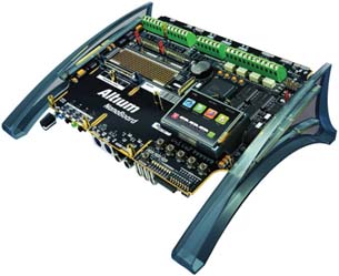
 Figure 4: The Altium Nanoboard 3000 is prototyping hardware that will let you comb the bugs out of your designs before your actual boards are ready. |
It’s not just for a pretty picture, either. You can do things with the models. You can export to MCAD programs like SolidWorks very easily, but that’s not where the real function (and fun) is. You can import MCAD models right into Altium Designer. And why would you want to do that, you ask? Remember those interferences Altium will show you? That’s right, it works in 3D mode, too. Altium Designer will tell you if parts won’t fit. It will perform x, y and z clearance checks. Clearance checking will highlight interferences. You can import an enclosure and check to see that your board will fit inside without poking through. Altium uses industry standard STEP to transfer files to and from MCAD. You can even link out to the model so an engineer can still make changes—and then later, update your models to stay current.
Altium also makes instant FPGA prototyping a breeze with its Nanoboard 3000 ($395, see Figure 4). This handy little piece of hardware lets you prototype all kinds of things with its modular design. You can program and debug your software, then upload it to your real hardware when it’s ready.
At about this point, you are probably wondering how much all of this is going to cost you. List price for the Board Implementation Suite is $4,995. The basic front-end license is $995. There is no official Mac version, but many Altium customers can run it with Windows emulation. It will run on a laptop, so you know it’s not a resource hog. Free tutorial videos are available on the Altium Wiki.
More Info:
Altium Limited
Mike Hudspeth, IDSA, is an industrial designer, illustrator and author who has been using a wide range of CAD and design products for more than 20 years. He’s DE’s expert in ID, design, rapid prototyping, and surface and solid modeling. Send him an email about this article at de-editors@digitaleng.news.
Subscribe to our FREE magazine, FREE email newsletters or both!


