Latest News
February 6, 2013
Ever put together one of those IKEA furniture that makes you feel dumb? The illustrated assembly instruction shows you exactly where each dowel, screw, or nail is supposed to go. But you can’t seem to complete that seemingly simple step. You find that the gap between the intersecting beams doesn’t leave enough room for your hand to tighten the screw, or that the dowel cannot be inserted unless you have an extra set of hands holding up another piece at a perfect angle. It’s not your fault. That’s the outcome when a manufacturer overlooks an essential factor in the assembling/dissembling process: the human factor.
Most manufacturers today use digital prototypes and digital simulation to accomplish what used to be done with physical mockups and physical tests. But the historical legacy and domain of the software tools they use is geometry, not human posture. Consequently, when these software programs automatically verify possible collisions and clearances, they’re looking for overlapping geometry; they seldom take into account how difficult or easy it is for someone—a human—to assemble the design.
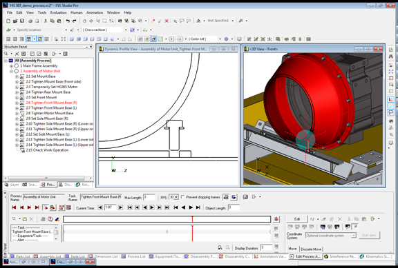
Bill Barnes, general manager of Lattice Technology, often cites a real-world customer case, where the designer missed a collision that would make assembling a design impossible. As shown in the 2D cross-section view above, the narrow gap between the chamber’s curved wall and the bracket leaves no room for the critical fasteners (in this case, the screws) to be removed or installed. You wouldn’t catch this type of error in standard collision-detection tools, Barnes pointed out, because the assembly, when presented with the screw tightened in a 3D model, won’t reveal any geometry flaws.
XVL Studio, Lattice Technology’s software program for publishing manufacturing instructions, allows you to specify tolerances when performing clearance checks. This gives you the option to add room for instrument removal and human hands, but keep in mind: Someone needs to think through the assembly/disassembly process to identify these potential clashes that needs verification. That’s something you can’t rely on the software to automatically figure out.
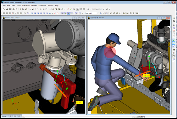
XVL Studio also offers the option to insert a human model with movable limbs. The simplest use of this may be to judge the size of the design (for example, a heavy machine) in proportion to a standard human worker. This will help identify problems with reaches and clearances in levers and knobs. For more detailed analysis, you can drag a digital manikin’s tool-grabbing hand to verify if it can make contact with the necessary hole, dial, or control panel without causing strain or stress on his/her body. For example, when you drag a manikin’s arm beyond a typical human’s range of motion, you get a red alert revealing problem with the manikin’s posture.
Lattice’s XVL format is one of the widely used 3D formats in automotive industry. Siemens PLM Software’s JT format also enjoys similar acceptance. Because fully detailed CAD files take a heavy tool on CPU performance, geometrically accurate but more compact lightweight formats emerge as better alternatives for manufacturing instructions and technical manuals. The XVL format, Barnes pointed out, offers better performance (responsiveness, speed, and accuracy) over other lightweight formats.
As a software package for publishing engineering instructions, XVL studio competes with other programs like Autodesk Inventor Publisher and Dassault Systemes’ 3DVIA Composer. Barnes pointed out that XVL Studio has additional features, such as the ability to create and organize 3D content as manufacturing bill of materials (BOM) in addition to the original CAD BOM. (Bear in mind: The way your create and group your subassemblies in a CAD file may be different from the way you’d organize them in an assembly manual intended for a repair technician’s use.)
Process simulation—for example, digitally simulating plant and factory operations using a software program—is a whole separate discipline, served by CAD and CAE (computer-aided engineering) software titans like Autodesk, Dassault Systemes, PTC, and Siemens PLM Software. Lattice’s technology is meant for producing interactive engineering instructions, modeling manufacturing activities, and collaboration. Because authoring tools like Lattice’s XVL Studio rely heavily on digital content (lightweight versions of CAD files) to produce assembly instructions, repair manuals, and training animations, it begins to face the same challenges seen in process simulation. Digitally simulating human behavior is, at least at the moment, an imperfect science.
Subscribe to our FREE magazine, FREE email newsletters or both!
Latest News
About the Author
Kenneth Wong is Digital Engineering’s resident blogger and senior editor. Email him at kennethwong@digitaleng.news or share your thoughts on this article at digitaleng.news/facebook.
Follow DERelated Topics


