Fortifying the MCAD-ECAD Bridge
CAD-embedded plug-ins, mergers and acquisitions, and the quest for common file formats reinforce works already in progress across the industry.
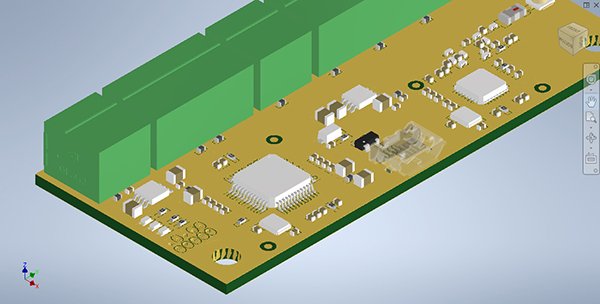
Component placement and copper definitions as defined in Altium ECAD environment are reflected in the 3D MCAD tool. Image courtesy of Altium.


Latest News
September 10, 2021
In early June, the design software giant Autodesk went after the popular electronic CAD (ECAD) software maker Altium. The company submitted a non-binding proposal to acquire all the outstanding shares of Altium Limited, stirring up excitement in the market.
The merger “would advance Autodesk’s strategy to converge design and make through a unified design, engineering and manufacturing cloud platform that enables greater productivity and sustainability for its customers,” wrote Autodesk in its press release.
Autodesk’s 2016 acquisition of CADSoft, developers of the ECAD software EAGLE, resulted in a rich set of ECAD tools nested inside Autodesk Fusion 360. With bidirectional data exchange between ECAD and MCAD objects, Fusion’s shared work environment allows both sides to be aware of the edits and revisions that take place in the electronics and the overall housing.
Altium 365, marketed as the “design platform that unites [printed circuit board] design, MCAD, data management and teamwork,” is well-known to the CAD users in the Autodesk Inventor, SolidWorks and PTC Creo communities. Many of them use the product to collaborate with ECAD designers. Autodesk’s ownership of Altium could have huge implications. It would give Autodesk greater control of the bridge that connects MCAD and ECAD.
“The real benefit of a CAD-embedded ECAD package happens when there’s a need to collaborate and unite both disciplines for joint products.”
However, the acquisition didn’t come to fruition. In July, Autodesk announced in another press release it had terminated discussions to acquire Altium.
“Autodesk has a long track record of disciplined strategic acquisitions,” said Andrew Anagnost, CEO of Autodesk. “While we did verbally improve our initial proposal, we were unable to agree on the basis to advance discussions. We respect the leadership team at Altium and wish them the best with their business.”
The news was bound to be greeted with some relief by Autodesk’s rivals. At the same time, it was sure to trigger greater discussions about the gateway between ECAD and MCAD, and the competitive advantages it brings to whoever controls the traffic through it.
What Brought MCAD and ECAD Closer
ECAD used to primarily be 2D diagrams that diagrammed out the components and connectivity in circuit boards. For a time, the ECAD and MCAD disciplines didn’t have a good reason to exchange data. The ECAD designer simply worked within the space constraint allotted to them; so long as they didn’t violate the space envelope, there was little or no need to communicate with the MCAD designer who worked on the overall housing and the product’s assembly.
But the miniaturization of products, a trend in the Internet of Things (IoT) era, brought the two disciplines closer than before, quite literally and figuratively. With electronics sitting close to other parts in tightly packed smart objects, such as smartphones, smartwatches and Wi-Fi-enabled thermostats, conflicts arose and unintended interferences became more common.
Let Us Meet on Neutral Ground
The biggest barrier to MCAD and ECAD collaboration is actually the discipline-specific software the two groups employ. The MCAD packages for mechanical designers and ECAD packages for electrical designers have standard libraries, geometry construction tools and terminologies that cater to their own sectors. Consequently, asking either side to switch to the preferred tool of the other party is an unfair demand.
CAD-embedded ECAD tools, such as those available inside Autodesk Fusion 360, PTC Creo MCAD-ECAD Collaboration Extension and Altium’s MCAD plug-ins, are a common way to bridge the two disciplines.
Many ECAD tools evolved to accommodate 3D viewing, which allows printed circuit boards (PCBs) and integrated circuits (ICs) to be designed in context alongside mechanical enclosures and other PCBs that might affect their placements.
“This makes them more MCAD-aware, but definitely doesn’t replace ECAD tools,” says Robert Haubrock, senior VP of product engineering software, Siemens Digital Industries Software. “Similarly, some MCAD tools have looked to build in PCB design functionality by combining ECAD and MCAD tools into a single embedded system, but that is only useful for the simplest of designs.”
“The real benefit of a CAD-embedded ECAD package happens when there’s a need to collaborate and unite both disciplines for joint products,” says Edwin Robledo, technical marketing manager of electronics at Autodesk.
Autodesk Fusion 360, an integrated CAD/CAM/CAE with cloud-hosted features, comes with an electronics workspace. It includes tools for length matching, manual routing, manufacture role check and PCB schematics. The user can export the completed PCB design as Gerber files for manufacturing using Fusion 360’s CAM processor. The built-in tool offers SPICE-based schematic simulation and design-rule checks before production.
Collaborative CoDesign
Altium CoDesigner is the MCAD-ECAD bridge for Quantel Laser, a division of Lumibird, a laser technology provider to the industrial, defense, scientific and medical sectors. In Quantel’s products, the PCBs and high-power diode drivers, control electronics and regulator electronics sit on top of one another in multiple stacks.
“Before we began using CoDesigner, we used to receive DXF files. We should then have to take the component and ask [the ECAD designer] how tall are these? Then we had to extrude the materials. We have some very tight-fitting applications,” says Laine McNeil, senior mechanical engineer at Quantel Laser.
The DXF file exported from ECAD includes the profile but not necessarily the height. The missing height is critical to MCAD users like McNeil, who designs the MCAD assembly that encompasses electronics. With CoDesigner McNeil feels he has a much better understanding of the physical geometry of the PCBs in the assembly.
In certain products, Jeremie Waller, senior electrical engineer at Quantel Laser, must work with McNeil early on to conceive a mechanical housing that can accommodate the complex electronics.
“I need to get him involved to show me where the mounting holes are,” he says.
CoDesigner can be installed as an add-on to popular MCAD packages, such as SolidWorks, Autodesk Inventor, Autodesk Fusion 360 and PTC Creo. The setup allows McNeil to work with his 3D SolidWorks files in a shared environment with his ECAD counterpart Waller.
The Push and Pull functions allow either side, MCAD or ECAD, to send and request revisions. This workflow eliminates the risk of one side designing something that will be a misfit for the other.
“We’re more competitive in the market because we can make our circuit boards smaller. And the space that [McNeil] is working with in his world is getting tighter and tighter,” says Walker.
Different Types of ECAD
With the letter “E” representing anything electronic, ECAD could mean software for designing PCBs or ICs. The distinction is important for those working in cross-disciplinary collaboration.
“When people say ECAD to MCAD, the question is: which ECAD? In fact, for many companies we are seeing engineering teams doing E/E systems design, so they’re collaborating between two ECAD design solutions and an MCAD solution, [so] talk about process complexity,” says A.J. Incorvaia, senior VP of electronic board systems, Siemens Digital Industries Software. “Only Siemens addresses all three domains with NX, Xpedition and Capital.”
Xpedition, Xpedition EDM and PADS Xpedition are part of Siemens’ Teamcenter product lifecycle management (PLM) framework. The products were originally developed by the semiconductor and chip design software maker Mentor Graphics, which Siemens acquired in 2016. It uses the incremental data eXchange format (IDX or EDMD, also known as ECAD design and MCAD design) to allow MCAD and ECAD designers to communicate the changes and revisions, which either side can accept or reject.
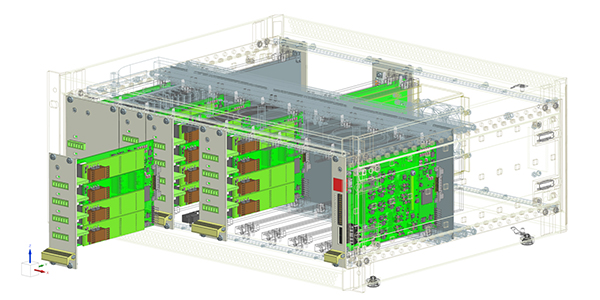
The Xpedition product line from Siemens allows ECAD designers to work in collaboration with NX CAD users. Image courtesy of Siemens.
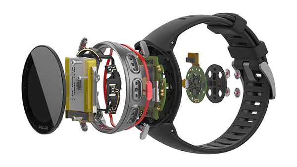
One of Siemens’ customers that uses the integrated approach is Polar Electro, a smartwatch maker. The IoT-enabled watches rely on software, hardware and electronics to connect to mobile phones, sensors and third-party apps.
The top-level PLM framework of the product is usually the starting point, says Hannu Hannila, senior consultant at CGI and former manager of PLM at Polar Electro. “After that, different teams can add their substructures, like mechanical design, electrical design and packaging designers … we integrated Siemens NX and Mentor Graphics tools into Teamcenter. We also manage our hardware-software compatibility in Teamcenter,” he explains.
Quest for a Common Language
Haubrock predicts the intermediate data format (IDF) will likely remain the interchange solution for the two disciplines.
“Engineers do not like change and will continue with a method that just works. Exposing customers to the latest method, IDX [supported by the Siemens Xpedition products] brings them a whole new world of capability and once transitioned … all formats have limitations. What Siemens has done is to extend the capability of IDX to provide an extended range of functions that are only possible between the Siemens toolsets, NX and Xpedition,” he explains.
Autodesk’s Robledo points to STEP and DXF as two common formats for MCAD-MCAD data exchange, but also notes their weaknesses.
“They aren’t designed to store an electronics netlist and other component information. These file formats are essentially just artwork, which limits their utility in an electronics workflow. And manually switching formats is inefficient and prone to introducing errors. That is why we designed [in] Fusion 360 to house everything under one roof, such as an electronic schematic editor, PCB layout, electronic component editor, mechanical workspace and much more,” he reasons.
“Regardless of the format, any file exchange brings some problems to the engineering workflow. Mechanical engineers get frustrated with losing MCAD constraints and references. Performance can be slow as it can take quite some time to generate those files. Moreover, they are always dealing with static files, and it can be difficult for both mechanical and electrical engineers to keep track of changes made on either side and of which version of the file is the latest,” says Nikolai Nyrkov, MCAD CoDesigner product manager at Altium.
Accelerating ECAD
- The growing complexity in simulation is not confined to the structural and fluid analyses commonly done in the mechanical domain. It has also reached semiconductor, electronics and electrical simulation, prompting many in the ECAD software sector to look for ways to parallelize the code.
“Even without simulation, we have a lot of cases where software performs a lot of complex calculations and users expect to have them in live mode—directly during PCB design. The most popular cases are [design rules check] and polygon repouring,” says Alexey Sabunin, global head of product marketing, Altium.
Tomek Brzuchacz, head of CAD software at Altium, also points to design rules check (DRC) as a good example of the type of operations that benefit from multicore processing.
“It’s a simple distance calculation upon a pair of geometry primitives. During the full board DRC, there could be millions of such pairs to be checked and that task can be efficiently performed by GPU [graphics processing units] in parallel to CPU operations. CPU is only needed to preprocess and arrange data for GPU calculations and aggregate the results,” he says.
In Altium Designer, the software harvests GPU processing to speed up:
- interactive 3D scene transformation for rigid/flex;
- polygon pouring (in the research phase);
- clearance boundaries visualization during interactive routing; and
- building hatched polygons.
“There are also efforts to utilize GPUs for limited simulation functions, and we see the use of GPU acceleration as important for the future to help deal with the complexity of product designs,” says Siemens’ Incorvaia.
The strictly 2D ECAD applications do not benefit much from the GPU, but the 3D workflow inside Fusion 360 does, according to Robledo.
“The future of consumer electronics engineering is heading toward a 3D modeling environment, meaning engineers will benefit from better hardware resources —especially graphics,” he says.
More Altium Coverage
More Autodesk Coverage
More Siemens Digital Industries Software Coverage
Subscribe to our FREE magazine, FREE email newsletters or both!
Latest News
About the Author
Kenneth Wong is Digital Engineering’s resident blogger and senior editor. Email him at kennethwong@digitaleng.news or share your thoughts on this article at digitaleng.news/facebook.
Follow DE