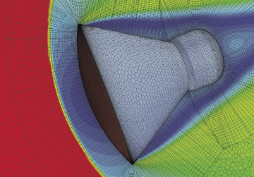
The Advancing Layer Mesher uses a pseudo-structured mesh approach to generate layered, primarily structured grids from wall boundaries beyond the boundary layer. This meshing approach is suitable for computations involving bow shocks, as depicted in this simulation of the re-entry of the Crew Exploration Vehicle. Image courtesy of CD-adapco.


March 29, 2014
p>
 The Advancing Layer Mesher uses a pseudo-structured mesh approach to generate layered, primarily structured grids from wall boundaries beyond the boundary layer. This meshing approach is suitable for computations involving bow shocks, as depicted in this simulation of the re-entry of the Crew Exploration Vehicle. Image courtesy of CD-adapco.
It’s easy to spot a bad mesh model, but a lot harder to know if a mesh model is good enough for what you need. That’s how John Chawner, president of simulation software developer Pointwise, sums up the dilemma of meshing.
Meshing—subdividing a 3D CAD model into tiny geometric elements—is largely automated these days, usually as a standard feature in preprocessing simulation programs. The software uses built-in algorithms to scan the imported CAD geometry, decide on the appropriate mesh to use, and create the mesh model. When something goes awry in the process, the signs are unmistakable. Instead of producing a mesh model, the software issues a failure alert. Or it produces a disfigured, twisted mesh model dramatically different from the original.
But in many cases, the software may just make educated guesses to resolve the conflicts and produce a mesh model. Based on experience, a simulation expert may be able to decide whether the software-produced mesh model is acceptable for the job at hand, be it flow simulation inside a pump or mechanical simulation of a landing gear. A non-expert unschooled in meshing principles, however, has few other choices but to trust the software-produced mesh model.
How can novice users determine whether the mesh model is good enough? Industry insiders point to a template-driven approach as the way of the future. They also say that, even if you end up taking a leap of faith in the software’s automatic meshing, it’s not exactly blind faith: Modern simulation software has built-in safeguards to prevent you from walking off the cliff.
Root Causes of Meshing Problems
Pierre Thieffry, ANSYS’ product manager for structural mechanics solutions, points to “dirty geometries that exhibit slivers, overlapping surfaces and holes” as a source of mesh failures. “Overly detailed geometry [or] models that contain too many details, some of which are not relevant to the model’s behavior” can also stump the automatic mesher, he adds.
Gilles Eggenspieler, senior fluid product line manager at ANSYS, notes that many simulation groups deal with CAD geometries with imperfections, such as gaps between surfaces, holes, etc. This is especially problematic for computational fluid dynamics (CFD) simulation, he adds, “because the first operation in every CFD simulation is to extract the fluid volume inside (internal flows) or outside (external flows) a given geometry.”
Design and simulation departments, although interdependent, treat geometry differently. As Eggenspieler points out, “A CAD file can incorporate bolt nuts, company logo, etc. Those details are important from a manufacturing point of view, but do not influence the flow behavior.”
The reality is, CAD-exported geometry is bound contain errors and flaws. “We made the decision that some user geometry is bound to be sloppily built or messy,” reports Pointwise’s Chawner. Accordingly, Pointwise’s products—and many others—shoulder the cleanup burden in the preprocessing phase of simulation.
Where Automation May Not be Ideal
Simulation products targeting nonexperts avoid overwhelming users by keeping required inputs to a minimum. Presenting the user with a long menu of mesh types to choose from, for example, could be a stumbling block. To bypass this, sometimes the automatic meshing feature might use a default mesh type that’s easier to automate, but may not be suitable for a particular problem.
“In the CFD community, we typically automate the meshing process by using unstructured meshes,” says Dave Corson, program manager for Altair Engineering’s AcuSolve. “Usually, that’s tetrahedral elements. This approach provides the most flexible and robust technique for handling arbitrarily complex geometry.”
But when the geometry is anisotropic—like the flow inside a long, skinny pipe—Corson says the mesh elements “should be stretched out in the direction of the liquid flow. Filling that type of volume with tetrahedral mesh is not such a good idea, because it uses far more elements than needed to be accurate.”
On the other hand, in a scenario like the leading edge of an airplane wing plowing into a high-gradient velocity field, the affected region requires special handling in the meshing process. To be able to detect such an exceptional case and create the appropriate mesh is “a tall order” for any software, Corson says.
The Healing Touches
ANSYS’s Thieffry notes that “for problematic geometry, we offer tools to clean it, both automated and manual. Our meshing tools also allow you to automatically or manually defeature a model.”
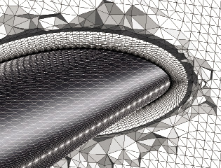 Unstructured mesh on a CFD volume, in AcuSolve. Image courtesy of Altair Engineering.
Automated defeaturing, Thieffry continues, takes into account the size of geometric elements such as edges or holes. “It can also detect proximity between similar entities—two close-enough edges that need to be pinched into one for the mesh, for example,” he says. “Manual defeaturing usually involves the use of what is called ‘virtual topologies,’ where users can group features or entities (edges, faces).”
Pointwise software uses two approaches to dealing with imperfections. According to the company, “The first approach is fault-tolerant meshing, in which we mesh the geometry as-is and then heal any problems on the mesh level. The second, newer approach is Solid Meshing. While importing CAD data into Pointwise, this technique creates models and quilts. Models are topological CAD entities that allow for watertight meshing over gaps and cracks in the underlying geometry. In addition to models, Pointwise includes the concept of meshing regions defined on the CAD level, also known as quilts. While a model is a watertight representation of the geometry, quilts are the regions within this model that hide unnecessary complex topology in the underlying geometry by identifying meshing region boundaries.”
In simulation software like Patran from MSC Software, users can rely on the free boundary check and free face check tools to identify geometry that needs to be patched before meshing.
“We have automatic healing, so [the software] looks at the flawed geometry and uses what it thinks is the best approach to clean it up,” explains Tim Kuhlmann, a product manager for MSC Software. Products that target more sophisticated users, he adds, are “less automatic” by design: With them, “you can drag and drop the edge lines to clean up the geometry.”
For simulating scenarios involving dense mesh in one area and coarse mesh in another area, Patran offers tools for mesh ceding and mesh zooming, Kuhlmann says.
The Penalty for Improper Meshing
Improper mesh—whether it results from automation or the user’s inexperience—affects the size of the model, and thus the time required to solve it. In quantitative terms, you pay for the wrong choices in higher CPU/GPU cycles and delays.
“In a massive 3D model, the use of tetrahedral elements has become prominent, even if hexahedral elements are necessary in some cases,” says ANSYS’ Theiffry, referring to elements such as crash analysis and some specific nonlinear models. “For thinner parts such as surface body, shell elements are usually preferred. And for truss-like structures, beam elements are preferred.”
ANSYS’ Eggenspieler points out that “A CFD tetrahedral or polyhedral mesh of a turbomachinery blade system is known not to be as accurate as a hexahedral mesh. In many cases, the mesh type is not critical, but the quality of the mesh is. CFD simulations require high quality meshes. If this is not the case, the simulation will either not be accurate or it will take a long time to converge—or both.”
Some software developers intend to circumvent the mesh-quality problem by making the solver technology insensitive to the mesh quality. “AcuSolve has made great strides in this area,” Altair’s Corson says. “Having a robust solver capable of handling badly distorted elements with high aspect ratios is one way to overcome the problems associated with automatic meshing.”
Bridging through CAD
If many imperfections are the outcome of CAD geometry export, then why not stop the problem right at the gate? That thinking, along with the vendors’ desire to make their tools more CAD-friendly for broader appeal, has led to the development of CAD-embedded simulation plug-ins.
“Our CAD client is a tool that embeds STAR CCM+ functionalities in popular CAD programs,” notes Joel Davison, a product manager from CD-adapco. “It offers a simplified front end for designers and nonexperts. It requires from you only a limited number of choices.”
Delphine Genouvrier, senior product portfolio manager for SolidWorks Simulation, observes that, with the tight integration of finite element analysis (FEA) and CFD tools inside CAD systems, “one of the values is geometry recognition and an intelligent-meshing methods. With SolidWorks Simulation, an automatic transitional mesher will refine mesh size for small entities and ensure proper mesh distribution between the refined areas and the rest of the model with transitional mesh.
“Moreover, the CAD integration offers tools to easily simplify and clean the CAD model for simulation purpose, such as the defeaturing for small fillets,” Genouvrier continues. “It enables as well to directly use the CAD boundary for automatic fluid domain creation for CFD analysis in SolidWorks Flow Simulation.”
Expert-built Templates
Some envision that, in the future, automatic meshing may behave more like artificial intelligence (AI): It would learn from past simulations performed, and apply the same approach in the future. Until that happens, however, it may be up to the users to feed that knowledge to nonexperts, in the form of templates.
“We have very good template-building tools,” said CD-adapco’s Davison. “An expert user can make a template file, so the nonexpert user can simply drop the geometry into the simulation tree and hit ‘Go.’ The advantage of that approach is, you are capturing your best practices. It’s a guided workflow, so the nonexpert only has to execute a string of commands.”
With this approach, simulation experts can develop templates for the most commonly executed jobs (for example, simulating wind tunnel tests for vehicles or turbo-machinery blade rows). For the type of geometry anticipated, the experts can specify in the template the recommended meshing procedures. This removes the burden from the nonexpert user.
More Info
Subscribe to our FREE magazine, FREE email newsletters or both!
About the Author
Kenneth Wong is Digital Engineering’s resident blogger and senior editor. Email him at kennethwong@digitaleng.news or share your thoughts on this article at digitaleng.news/facebook.
Follow DE